Squirrel on Electric Imp #require “JSONEncoder.class.nut:2.0.0” local number = 1523187384; local record = array(4); local result = 0; local byteArray = array(4); local record2 = array(4); local result2 = 0; local byteArray2 = array(4); // method 1 and before shift right record[0] = ((number & 0xff000000) >> 24); record[1] = ((number & 0x00ff0000) >> 16); […]
How to get UART serial ports working on the beaglebone black. The BBB by default has the UART pins set as normal GPIO pins so they need to be changed to UART pins first before they will work. I saw the problem with trying a few different programming languages including python and Node-Red. With Node-Red […]
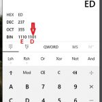
When assigning MAC addresses to your projects, it’s helpful to understand a bit about them. Most know that there are some IP addresses that can be used safely in a private network, but what about MAC addresses? Well MAC addresses have a bit in them that defines if they are a universally assigned MAC address, […]
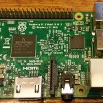
Trying to get WiFi working on the Raspberry Pi 3 following the instructions found at https://www.raspberrypi.org/documentation/configuration/wireless/wireless-cli.md when I got to start the WiFi using sudo wpa_cli reconfigure It reports an error: Failed to connect to non-global ctrl_ifname: (null) error: No such file or directory Error messages like this are great as they don’t provide any clue’s, […]
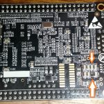
If you have a Beaglebone black and when you apply power you get a short flash on the power LED, one thing to check is if the board is damaged. We show how in this short note. It took a while but found that checking if the resistance across C15 on the bottom of the […]
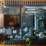
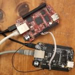
This is specific for the Beaglebone Black model C sold through Element 14 which includes retailers like Adafruit. There is quite a bit of info out on the net on how to enable the UART’s but for some reason, locations of things have changed. To check if this instruction is going to be valid for […]
Into 3D printing? The Stackexchange site is about to put into beta a 3D Printing Q&A site and are looking for enthusiastic people to join at the start. Click on image to sign up.
Download, unzip and copy the DHT22 folder into your libraries folder eg: for MPIDE: C:\Users\yourname\Documents\mpide\libraries\DHT22 for Arduino IDE: C:\Users\yourname\Documents\Arduino\libraries\DHT22 An example script is included. Been reading a few reports that this sensor is more accurate at the higher voltage (eg 5V) rather than the 3.3V. My observations so far suggest the same. So when using […]
Small example to show how to use pointers to return more than one (1) variable from a function in C or C++
For those wanting to develop with USB, a brilliant resource is USB in a NutShell, My ventures showed while USB is very easy at the user level, it’s far from it at the developer level. Its really a specialty in it’s own right. My first venture into this area was developing a set of rudder […]