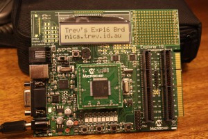
My Explorer 16 development board arrived yesterday so have been playing with it. Initially the example code that came with the PIC24FJ128GA010, doing some basic things like modifying the looping LCD text, then writing my first program to test the LED’s on the board. Had to make sure it all worked. And as usual stuff from Microchip just worked. For those that might have just bought one because they are on the same journey I’m on, begining with the PIC24, here is the source so you can make sure your LED’s are working.
#include <p24FJ128GA010.h>

int main()
{
    AD1PCFG = 0xffff; // configure PortA as digital
    TRISA = 0x0000; // configure PortA as output

    while(1) {
        // Turn on the LED's
        LATAbits.LATA0 = 1;
        LATAbits.LATA1 = 1;
        LATAbits.LATA2 = 1;
        LATAbits.LATA3 = 1;
        LATAbits.LATA4 = 1;
        LATAbits.LATA5 = 1;
        LATAbits.LATA6 = 1;
        LATAbits.LATA7 = 1;

        // delay for about 500mSecs
        msDelay(500);

        // turn of the LED's
        LATAbits.LATA0 = 0;
        LATAbits.LATA1 = 0;
        LATAbits.LATA2 = 0;
        LATAbits.LATA3 = 0;
        LATAbits.LATA4 = 0;
        LATAbits.LATA5 = 0;
        LATAbits.LATA6 = 0;
        LATAbits.LATA7 = 0;

        // delay for aprox 500mSec
        msDelay(500);
    }
}

int x=0;

void msDelay(int d) // The delay routine
{
    while (d>0) {
        for (x=0; x<500; x++) {
        }
        d--;
    }
}
Assuming you know how to create a project in MPLab, build it and then program the chip you shouldn’t have any problems.
Next will be re-write this to use a timer and interrupt to do the timing releasing the main loop for other things.
(Note: I’m going to leave this code as is as it reminds me of progress. While it works, there are far more elegant ways of writing this.)
