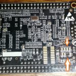
Posts Tagged “LED”

This fix refers to the library version release 12 April 2011. When using an Explorer 16 board and setting the Macro definition of EXPLORER16_100P in MPLab, parts of the library do not pick it up correctly rendering the heartbeat LED and the UART to not work. No compilor error is noticed.

In the file lib\include\pic24_libconfig.h at line 76, change the following section of code:

/** Select one of the hardware platform above to compile for. */
#ifndef HARDWARE_PLATFORM
#define HARDWARE_PLATFORM DEFAULT_DESIGN
#endif
// Verify that a valid hardware platform is selectd
#if (HARDWARE_PLATFORM != EXPLORER16_100P)   && \
    (HARDWARE_PLATFORM != DANGEROUS_WEB)     && \
    (HARDWARE_PLATFORM != STARTER_BOARD_28P) && \
    (HARDWARE_PLATFORM != DEFAULT_DESIGN)
#error Invalid hardware platform selected.
#endif
//@}

Replacing the above code with this code:

/** Select one of the hardware platform above to compile for. */
/* The automated method expects the board is defined in MPLAB
   using Use Project->Build Options-> Project, click on
   the MPLAB C30 tab, and in Macro Definitions click 'Add',
   and add:
      - For the Explorer 16 board - EXPLORER16_100P
      - For the Dangerous Prototypes web server - DANGEROUS_WEB
      - For the Microchip 16-bit 28-pin Starter Board - STARTER_BOARD_28P
   If the above is not set, the code will compile with the default
   of DEFAULT_DESIGN
*/
#ifndef HARDWARE_PLATFORM
#ifdef EXPLORER16_100P
#define HARDWARE_PLATFORM EXPLORER16_100P
#elif STARTER_BOARD_28P
#define HARDWARE_PLATFORM STARTER_BOARD_28P
#elif DANGEROUS_WEB
#define HARDWARE_PLATFORM DANGEROUS_WEB
#else
#define HARDWARE_PLATFORM DEFAULT_DESIGN
#endif
#endif
// Verify that a valid hardware platform is selectd
#if (HARDWARE_PLATFORM != EXPLORER16_100P)   && \
    (HARDWARE_PLATFORM != DANGEROUS_WEB)     && \
    (HARDWARE_PLATFORM != STARTER_BOARD_28P) && \
    (HARDWARE_PLATFORM != DEFAULT_DESIGN)
#error Invalid hardware platform selected.
#endif
//@}

This will now pick up the Macro definition set in MPLab and compile the components of the library needed for the Explorer 16 to function.

So far have tested the above with the Explorer 16, PIC24HJ256GP610A PIM, and the reset.c example from chapter 8 in the Microcontrollers: From Assembly Language to C Using the PIC24 Family.

Comments No Comments »

Hi again. Onto the next example, this time on page 295 (figure 8.28). The code for this one is called ‘ledtoggle_nofsm’ and it’s in the chap8 folder.

Now that we’ve defined EXPLORER16_100P in the pic24_all.h file, here is a new checklist to use:

  1. Double click on the project file for the exercise your wanting to do. (Make sure you don’t already have MPLAB open or it will complain)
  2. Set the processor type in the menu item Configure – Select Device. The default PIC24 that comes with the Explorer16 is PIC24FJ128GA010.
  3. Remove the linker script from the workspace files viewer under “Linker Scripts” (don’t add anything, MPLAB will manage it for you)
  4. Change from DEBUG to RELEASE in the drop down at top of MPLAB screen
  5. Select your programmer (Programmer – Select Programmer). I use the ICD2
  6. Make required changes to the code (see below for this exercise)
  7. CTRL-F10 to build all
  8. When you get the BUILD SUCCEDED message, program the chip (Programmer – Program)
  9. Click ok the the ICDWarn0046 warning (unless you’ve got sick of this message and clicked the “don’t show me again” like I did)
  10. disconnect the ICD2 when the programmer has completed.

Here is the modification needed for this one to work. Shown here is the code between the #include directive and the start of the main() function.

You should see the very left LED blinking. When you press the right of the 4 buttons, the second from left LED should toggle (light up if it’s the first press). Keep pressing and releasing and observe what happens. You will notice the LED state doesn’t change until the button is released.

#include "pic24_all.h"

/** \file
A program that toggles an LED whenever a pushbutton switch is pressed
and released. Does not use a finite statement approach.
*/

#if defined(EXPLORER16_100P)

/// LED1
#define CONFIG_LED1() CONFIG_RA6_AS_DIG_OUTPUT()
#define LED1  _LATA6    //_LATA6 is port register for RA6
#warning Were using the explorer16 version of the code
/// Switch1 configuration
inline void CONFIG_SW1()  {
  CONFIG_RD13_AS_DIG_INPUT();     //use RD13 for switch input
  ENABLE_RD13_PULLUP();           //enable the pullup 
}
#define SW1              _RD13       //switch state

#else  // not Explorer16

/// LED1
#define CONFIG_LED1() CONFIG_RB14_AS_DIG_OUTPUT()
#define LED1  _LATB14     //led1 state
#warning If your using an Explorer16, this program wont work
/// Switch1 configuration
inline void CONFIG_SW1()  {
  CONFIG_RB13_AS_DIG_INPUT();     //use RB13 for switch input
  ENABLE_RB13_PULLUP();           //enable the pullup 
}
#define SW1              _RB13       //switch state

#endif  // if defined EXPLORER16_100P

#define SW1_PRESSED()   SW1==0  //switch test
#define SW1_RELEASED()  SW1==1  //switch test

int main (void) {
.....

Example 7 which is Figure 8.30 on page 298 is called ledtoggle and is in the chap8 folder. It’s the same changes as example 6 above except the original code has some extra bits that example 6 didn’t have.

#include "pic24_all.h"

/** \file
A program that uses a finite state machine approach for
toggling an LED whenever a pushbutton switch is pressed
and released. Demonstrates the use of debounce delays when
polling a switch input.
*/

#if defined(EXPLORER16_100P)

/// LED1
#define CONFIG_LED1() CONFIG_RA6_AS_DIG_OUTPUT()
#define LED1  _LATA6    //_LATA6 is port register for RA6
#warning Were using the explorer16 version of the code

/// Switch1 configuration
inline void CONFIG_SW1()  {
  CONFIG_RD13_AS_DIG_INPUT();     //use RD13 for switch input
  ENABLE_RD13_PULLUP();           //enable the pullup
}
#define SW1              _RD13       //switch state

#else  // not Explorer16

/// LED1
#define CONFIG_LED1() CONFIG_RB14_AS_DIG_OUTPUT()
#define LED1  _LATB14     //led1 state
#warning If your using an Explorer16, this program wont work

/// Switch1 configuration
inline void CONFIG_SW1()  {
  CONFIG_RB13_AS_DIG_INPUT();     //use RB13 for switch input
  ENABLE_RB13_PULLUP();           //enable the pullup
}
#define SW1              _RB13       //switch state

#endif  // if defined EXPLORER16_100P

#define SW1_PRESSED()   SW1==0  //switch test
#define SW1_RELEASED()  SW1==1  //switch test

typedef enum  {
.....

Comments No Comments »

Continuing with Chapter 8, the next file is the one referred to in Figure 8:5 Improved code example for flashing LED. It takes the previous one and modifies it using macro’s. Well we sort of used macros in the last one to break out the Explorer 16 version and the original. This file is called “ledflash” and it’s also in the chapter 8 folder.

You will see what the author had in mind. The use of macro’s certainly makes it easier to see what is going on. Here is the modified code that enables the Explorer 16 to run this. Don’t forget to define EXPLORER16_100P.

#if defined(EXPLORER16_100P)
#define CONFIG_LED1() CONFIG_RA6_AS_DIG_OUTPUT()
#define LED1 _LATA6 //_LATA6 is port register for RA6
#warning Were using the explorer16
#else // not Explorer16
#define CONFIG_LED1() CONFIG_RB15_AS_DIG_OD_OUTPUT()
#define LED1 _LATB15 //_LATB15 is port register for RB15
#warning Were not using the explorer16 because EXPLORER16_100P not defined
#endif // if defined EXPLORER16_100P
int main(void) {
  configClock();
  /********** GPIO config **********/
  CONFIG_LED1();
  LED1 = 0;
  while (1) {
    DELAY_MS(250); //delay long enough to see LED blink
    LED1 = !LED1; // Toggle LED
  } // end while (1)
}

This time all the configuration changes needed are done in the short macro section while leaving the actual code identical effectively creating a hardware abstraction layer between the code and the hardware.

Ok so now time to build. Here is a check list to follow for these examples.

  1. Define EXPLORER16_100P (Project – Build Options – Project. Then the MPLAB C30 tab. Add the preprocessor macro.
  2. Remove the linker script from the workspace files viewer under “Linker Scripts” (dont add anything, MPLAB will manage it for you)
  3. Change from DEBUG to RELEASE in the drop down at top of MPLAB screen
  4. Select your programmer (Programmer – Select Programmer). I use the ICD2
  5. CTRL-F10 to build all
  6. When you get the BUILD SUCCEDED message, program the chip (Programmer – Program)
  7. Click ok the the ICDWarn0046 warning
  8. disconnect the ICD2 when the programmer has completed.

You should now see the LED connected to RA6 (second from left) flash at about 1 per second.

One thing I do want to point out, I am not going to teach you about programming and the PIC etc. The intent of this blog is share my adventures and if you happen to learn something from that, well that’s good. The other thing I’m going to recommend is to buy the book referred to here. See the books web site here. This is also the web site where you will find all the original code the book discusses and what I refer to here.

Comments No Comments »

This is my Explorer 16 Development Board.

My Explorer 16 Development Board with the 2nd PicTail Plus connector already soldered to the board.

My Explorer 16 development board arrived yesterday so have been playing with it. Initially the example code that came with the PIC24FJ128GA010, doing some basic things like modifying the looping LCD text, then writing my first program to test the LED’s on the board. Had to make sure it all worked. And as usual stuff from Microchip just worked. For those that might have just bought one because they are on the same journey I’m on, begining with the PIC24, here is the source so you can make sure your LED’s are working.

Very basic, just flashes all 8 LED’s on then off about once per second.

#include <p24FJ128GA010.h>

int main()
{
  AD1PCFG = 0xffff; // configure PortA as digital
  TRISA = 0×0000; // configure PortA as output

  while(1)
  {
    // Turn on the LED’s
    LATAbits.LATA0 = 1;
    LATAbits.LATA1 = 1;
    LATAbits.LATA2 = 1;
    LATAbits.LATA3 = 1;
    LATAbits.LATA4 = 1;
    LATAbits.LATA5 = 1;
    LATAbits.LATA6 = 1;
    LATAbits.LATA7 = 1;

 // delay for about 500mSecs
    msDelay(500); 

 // turn of the LED’s
    LATAbits.LATA0 = 0;
    LATAbits.LATA1 = 0;
    LATAbits.LATA2 = 0;
    LATAbits.LATA3 = 0;
    LATAbits.LATA4 = 0;
    LATAbits.LATA5 = 0;
    LATAbits.LATA6 = 0;
    LATAbits.LATA7 = 0;

 // delay for aprox 500mSec
    msDelay(500);
  }
}

int x=0;

void msDelay(int d) // The delay routine
{
  while (d>0)
  {
    for (x=0; x<500; x++)
    {
    }
  d–;
  }
}

Assuming you know how to create a project in MPLab, build it and then program the chip you shouldn’t have any problems.

Next will be re-write this to use a timer and interupt to do the timing releasing the main loop for other things.

 (Note: I’m going to leave this code as is as it reminds me of progress. While it works, there are far more elegant ways of writing this.)

Comments No Comments »